
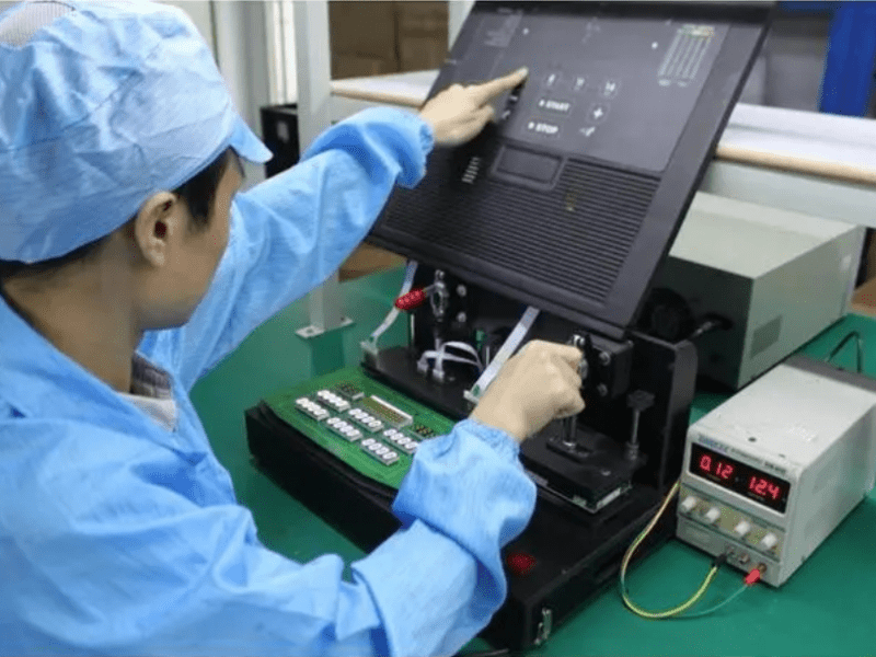
Functional circuit testing verifies that a finished electronic assembly performs as intended before it moves into integration, shipment, or field use. This service is designed for teams that need more than basic inspection: it checks real circuit performance against defined operating conditions, expected outputs, communication behavior, and product-specific limits. Whether you are building a prototype run or scaling through pcb contract manufacturing, a structured Functional Circuit Test helps expose performance issues while they are still practical to correct.
What Does Functional Circuit Test Include?
Functional Circuit Test includes the planning, setup, execution, and reporting needed to confirm that a powered circuit behaves correctly in its intended operating mode. Instead of only checking whether components are present, functional testing applies signals, loads, power, firmware interactions, or communication checks so the assembly can be evaluated as a working product. The exact test procedures depend on your design, but the goal is always the same: verify that the pcb assembly can do the job it was built to do.
A typical functional testing package can include:
- Test strategy review based on schematics, bill of materials, firmware needs, product risk, and production volume.
- Power-up and current checks to confirm safe start-up behavior and identify shorts, abnormal loads, or unstable rails.
- Input and output validation for switches, sensors, relays, LEDs, displays, drivers, connectors, and other interface points.
- Signal and circuit analysis using defined pass/fail limits for voltage, timing, frequency, resistance, or communication response.
- Fixture or harness planning so repeatable contact can be made with test pads, connectors, or external interfaces.
- Documented results that support troubleshooting, production release, and continuous improvement in future builds.
Built to Verify Real Circuit Performance
A visual inspection, automated optical inspection, or continuity check can catch many manufacturing issues, but those methods do not prove that the circuit works under operating conditions. Functional testing fills that gap by evaluating behavior after assembly, soldering, programming, and interconnection have all come together. For an smt pcba with mixed analog, digital, power, and communication sections, this is often the first point where the full design can be judged as a working system.
This matters because many faults are conditional. A component may be placed correctly but have the wrong value. A solder joint may pass a basic check but fail when current demand rises. A communication line may appear intact but respond incorrectly when the firmware runs. Functional Circuit Test turns those hidden risks into measurable observations, helping engineering and manufacturing teams focus on the issue instead of guessing where the failure began.
The practical benefit is faster decision-making. If a board passes, it can move forward with greater confidence. If it fails, the recorded symptom gives technicians and engineers a clearer starting point for diagnosis. Over time, the same data can reveal patterns tied to design margins, component variation, handling, programming, or test coverage.
Techniques Matched to Your Product Risk
Functional circuit testing is not one fixed method. It is a set of electrical testing techniques chosen around the product’s purpose, complexity, and failure risk. A simple Consumer Electronics board may need a concise power, button, LED, and communication sequence, while a Medical Devices controller or Industrial Control & Automation module may require deeper circuit analysis, controlled stimuli, and more detailed documentation.
Useful techniques may include:
- Power sequencing tests: Confirm that voltage rails start in the expected order and remain stable during operation.
- Load and output checks: Exercise drivers, relays, motors, heaters, indicators, or output channels under defined conditions.
- Sensor and input simulation: Apply known signals so firmware and hardware responses can be measured consistently.
- Communications testing: Verify interfaces used in Communications & Networking products, including response behavior, addressing, or data transfer at the product level.
- Boundary-condition checks: Test selected edge cases, such as low input voltage, maximum expected load, or alternate operating modes when those limits are defined.
- Firmware-assisted testing: Use embedded diagnostics, test modes, or command responses to confirm board-level function.
- Failure isolation support: Capture measurements that help distinguish a manufacturing defect from a design, programming, or component issue.
The right mix depends on what the circuit must prove before it leaves production. A high-volume board may need a streamlined test that runs quickly and consistently. A complex early build may benefit from broader measurements that help refine the design and test procedures before production ramps.
Service Specifications Are Defined Around Your Assembly
Because every circuit is different, a strong functional testing plan starts with the product requirements rather than a generic checklist. The specification should define what is powered, what is stimulated, what is measured, and what counts as a pass or fail. This prevents vague testing and gives production teams a repeatable standard.
Key items to define include:
- Unit under test configuration: Identify the pcb assembly revision, firmware version, programmed settings, cables, accessories, and any required mating equipment.
- Power and environmental assumptions: State the input voltage, current expectations, operating modes, warm-up needs, and any special handling requirements. If temperature, load, or duty cycle matters, those limits should be included in the plan rather than assumed.
- Measurement points and limits: Define the signals, connectors, test pads, or outputs to be measured. Pass/fail limits should be realistic, tied to the design, and clear enough for repeatable production use.
- Test sequence and operator actions: Document the order of steps, required prompts, safety checks, programming actions, and expected responses. A good sequence reduces operator interpretation and improves consistency.
- Result capture and traceability: Decide whether the output is a simple pass/fail result, a detailed measurement log, serialized record, defect category, or engineering report.
These details also support better communication between design engineering, test engineering, and pcb contract manufacturing partners. When the expected behavior is written clearly, problems are easier to reproduce and correct.
Applications Across Electronics Markets
Functional circuit testing is valuable wherever a board’s failure could create returns, downtime, safety concerns, or expensive rework. The depth of testing should reflect the risk of the product and the cost of a missed defect.
Common applications include:
- Automotive Electronics: Control modules, sensor interfaces, lighting assemblies, power distribution boards, and communication circuits that must operate reliably within a larger vehicle system.
- Medical Devices: Control electronics, user interfaces, monitoring circuits, and connected modules where documented test procedures and predictable behavior are essential.
- Industrial Control & Automation: I/O modules, motor control boards, relay interfaces, machine controllers, and monitoring hardware exposed to demanding operating environments.
- Communications & Networking: Router, gateway, interface, and connected-device assemblies that rely on correct signal behavior and dependable data exchange.
- Consumer Electronics: Wearable, smart device, audio, lighting, appliance, and accessory boards where functional failures can quickly become warranty or user-experience problems.
For each market, the test should reflect the product’s actual use. A connected device may need communication verification. A power board may need load behavior and thermal assumptions reviewed. A control module may need input simulation and output response checks. The value comes from testing what matters, not from adding unnecessary steps.
From Prototype Insight to Production Control
Functional testing is useful at more than one stage of the product lifecycle. During prototype builds, it helps engineers understand whether the design performs as expected and where margins may need improvement. During production, it becomes a repeatable quality gate that catches assembly or programming issues before boards are installed into higher-level systems.
A practical workflow often looks like this:
- Review the design intent to understand critical functions, risk areas, interfaces, and expected operating modes.
- Create the test plan with defined electrical testing steps, pass/fail limits, fixture needs, and data requirements.
- Validate the procedure on known-good and known-fault units when available, adjusting steps that are unclear or unreliable.
- Run production testing using consistent operator instructions, controlled equipment, and repeatable measurement points.
- Analyze failures so defect trends can feed back into circuit design, smt pcba process controls, component selection, or handling methods.
This approach keeps testing connected to both engineering and manufacturing. It can support a small engineering build, a pilot run, or an ongoing production program without losing sight of the same core question: does the circuit perform correctly when used as intended?
Pricing Is Based on Test Coverage and Production Needs
Functional circuit testing pricing depends on the complexity of the pcb assembly, the number of functions to verify, the fixture or harness requirements, software or firmware interaction, reporting needs, and expected production volume. A simple board with accessible connectors may require only a lean procedure, while a dense mixed-signal assembly may need custom fixtures, automated measurements, and deeper documentation.
To prepare an accurate quote, gather the items that define the work:
- Schematics, assembly drawings, and bill of materials.
- PCB layout or test pad information when fixture access is needed.
- Firmware files, programming instructions, or diagnostic command details.
- Product requirements, expected outputs, and critical tolerances.
- Sample boards, known-good references, or examples of common failures if available.
- Estimated build quantity and preferred reporting format.
If some details are not yet finalized, the test plan can still begin at a concept level. Early planning often improves design-for-test access and prevents last-minute changes when the board is already in production.
Start with a Test Plan Built for Your Product
A Functional Circuit Test should be specific enough to protect product quality and practical enough to run in the real manufacturing flow. When the procedure reflects the actual circuit, the result is more than a pass/fail label; it becomes a useful control point for quality, troubleshooting, and production confidence.
Share your pcb assembly details, target functions, and production goals to begin shaping a functional testing approach. From there, the next step is to define the required coverage, identify fixture or equipment needs, and turn your product requirements into clear, repeatable test procedures.
FAQ
What is Functional Circuit Testing (FCT)?
Functional Circuit Testing (FCT) is a PCBA testing method that verifies whether a fully assembled board performs its intended electrical functions under defined operating conditions. Unlike ICT or AOI, FCT powers up the board and simulates real inputs, loads, and communication signals to confirm the design works as a complete system before shipment.
What is the difference between ICT and FCT?
ICT (In-Circuit Test) checks individual component values, solder joints, and connections one by one using a bed-of-nails or flying probe fixture. FCT tests the board as a working product — applying power, signals, and firmware interaction to confirm overall functionality. ICT catches manufacturing defects; FCT confirms the design performs as intended.
Which industries use Functional Circuit Testing?
FCT is widely used in Automotive Electronics (ECU, BMS, ADAS), Medical Devices (diagnostic and monitoring equipment), Industrial Control & Automation (I/O modules, motor controllers), Communications & Networking (routers, gateways), Consumer Electronics (wearables, smart devices), Aerospace & Defense, and Energy & Power Electronics.
How much does Functional Circuit Testing cost?
FCT pricing depends on board complexity, number of functions to verify, fixture or harness requirements, firmware interaction, reporting needs, and production volume. A simple board with accessible connectors may need only a lean procedure, while dense mixed-signal assemblies require custom fixtures and deeper documentation.
What information is needed to quote a Functional Circuit Test?
To prepare an accurate quote, provide: schematics, assembly drawings and BOM, PCB layout or test pad details, firmware files or programming instructions, product requirements and critical tolerances, sample boards or known-good references, and estimated build quantity.
Need a reliable Functional Circuit Testing partner for your PCBA project?
Greenspcba Technology provides structured FCT services for automotive, medical, industrial, and consumer electronics assemblies. From test plan design to fixture development and production testing, we help you catch defects before they reach your customers. Contact us with your BOM and Gerber files for a 24-hour quote.
Recent Comments