
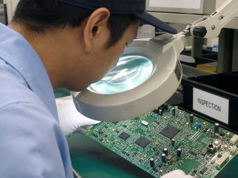
Manual Visual Inspection is a disciplined quality control method that uses trained human judgment to identify defects, process variation, workmanship issues, and cosmetic concerns that may not be fully captured by automated systems alone. In manufacturing environments such as SMT PCBA manufacturing, medical electronics assembly, and other precision industries, it works best as part of a wider quality assurance inspection strategy rather than as a stand-alone checkpoint. This guide explains where manual inspection fits, how to reduce inspection errors, and how to build a practical process that supports consistent product quality.
What Role Does Manual Visual Inspection Play in Quality Control Inspection?
Manual Visual Inspection helps manufacturers verify whether a product, assembly, or component meets defined workmanship and acceptance criteria before it moves to the next process step or ships to a customer. It is especially valuable when the defect requires context, interpretation, or judgment: a marginal solder fillet, a surface blemish, a missing label, a polarity concern, contamination, incorrect orientation, or a workmanship issue that looks unusual but not necessarily measurable by a machine.
In a strong quality control inspection program, manual inspection is not simply “looking at the product.” It is a controlled activity based on visual inspection standards, trained inspectors, documented criteria, proper lighting and magnification, and clear defect classification. The goal is not to rely on eyesight alone; the goal is to combine human pattern recognition with a repeatable inspection method.
Manual inspection also acts as a feedback loop. When inspectors repeatedly find the same defect, the discovery should trigger process investigation, not just rework. A solder bridge, tombstoned component, scratched housing, or poor marking may point to fixture wear, handling problems, stencil issues, incorrect profiles, supplier variation, or gaps in operator training.
For products with higher risk profiles, such as medical-electronics-pcba assemblies, manual inspection can add a practical layer of control. It allows teams to review workmanship details that may affect performance, reliability, traceability, or customer acceptance. The best outcomes come when inspection findings are captured, trended, and used to improve the process upstream.
Manual Inspection as Part of a Complete Quality System
Manual Visual Inspection should sit inside a broader quality system that includes incoming inspection, in-process controls, automated inspection where appropriate, functional testing, documentation review, and final release checks. Each activity catches a different type of risk. Manual inspection is strongest when the product requires judgment, surface-level assessment, or confirmation against workmanship standards.
A quality assurance inspection program focuses on preventing defects and proving that a controlled process is being followed. A quality control inspection program focuses on identifying and containing defects in actual output. In practice, manufacturers need both. Quality assurance builds the system; quality control verifies the result.
Manual inspection connects those two ideas. It confirms product condition while revealing whether the process is drifting. For example, if an inspector sees inconsistent solder wetting across several boards, the finding may indicate a process variable that needs attention. If the same cosmetic mark appears on multiple housings, the team may need to investigate packaging, tooling, or handling.
This is why manual inspection should be treated as data-producing work. Checklists, nonconformance records, defect codes, photos, lot history, and disposition notes all matter. Without documentation, inspection becomes subjective and difficult to improve. With documentation, it becomes a source of quality intelligence.
Where Manual Inspection Adds the Most Value
Manual inspection is particularly useful in situations where automated inspection is limited by geometry, material variation, reflective surfaces, complex assemblies, or subtle workmanship criteria. It also helps when the product has a low-volume or high-mix profile, where programming automated systems for every configuration may not be practical.
In SMT PCBA manufacturing environments, automated optical inspection can quickly evaluate many placements and solder joints, but human review may still be needed for ambiguous conditions, first-article builds, rework verification, connector inspection, conformal coating checks, wire routing, label placement, mechanical hardware, and final assembly appearance. The inspector can interpret the assembly in a way that connects design intent, customer requirements, and workmanship expectations.
Manual inspection also supports containment. If a defect is found at final inspection, a trained inspector can help determine whether it appears isolated, repeated, process-related, or handling-related. This does not replace engineering analysis, but it provides useful evidence for disposition and corrective action.
Common areas where manual inspection is valuable include:
- Incoming materials: confirming visible damage, packaging condition, contamination, labeling, color, finish, or obvious mismatch.
- In-process production: checking workmanship after soldering, bonding, fastening, coating, machining, printing, assembly, or packaging steps.
- First-article builds: reviewing whether the first output from a setup aligns with drawings, specifications, and customer requirements.
- Rework verification: confirming that corrected parts meet the same acceptance criteria as originally manufactured parts.
- Final inspection: verifying that the finished product is complete, clean, labeled, documented, and visually acceptable before release.
- Customer-specific requirements: checking attributes that are important to a particular use case, drawing note, or approved quality plan.
The practical benefit is flexibility. A human inspector can adapt to product variation, notice unexpected issues, and escalate concerns that fall outside a narrow programmed rule.
What Causes Manual Visual Inspection Error Rates in Manufacturing?
Manual visual inspection error rates in manufacturing are influenced by human factors, process design, product complexity, inspection conditions, and the clarity of the acceptance criteria. Errors can occur when inspectors miss actual defects, reject acceptable product, apply standards inconsistently, or make decisions without enough information. The goal is not to pretend manual inspection is perfect; the goal is to design the process so the inspector has the best possible chance of making the right decision.
The phrase manual visual inspection error rate manufacturing is often used when teams are trying to understand why defects escape inspection or why inspectors disagree. The answer is rarely one single cause. More often, error rates reflect a combination of fatigue, ambiguous criteria, rushed throughput, poor lighting, inadequate magnification, inconsistent training, similar-looking parts, unclear defect examples, and weak feedback from downstream failures.
A common mistake is blaming the inspector before examining the system. If the workstation is poorly lit, the product is difficult to orient, the standard is vague, and production pressure discourages careful review, errors are predictable. Better inspection results come from improving the environment, the method, and the decision support around the inspector.
Human Factors That Affect Inspection Accuracy
Human attention naturally changes over time. Repetitive visual work can lead to fatigue, especially when most parts are acceptable and defects are rare. This makes it harder to maintain the same level of vigilance throughout a long inspection period. Rotating tasks, scheduling breaks, and avoiding unrealistic inspection speeds can reduce risk.
Visual acuity also matters. Inspectors may need periodic vision checks, appropriate corrective lenses, and access to magnification tools. Even a skilled inspector can struggle if the feature is too small, contrast is low, or the defect appears only at a certain angle.
Decision fatigue is another factor. If acceptance criteria require frequent judgment calls with limited examples, inspectors may become inconsistent. Clear criteria, boundary samples, defect libraries, and escalation rules help reduce that burden.
Process Factors That Create Avoidable Variation
Manual inspection becomes less reliable when the process is not standardized. If each inspector uses a different viewing angle, sequence, magnification level, or checklist, the results will vary. A repeatable inspection route helps ensure that critical areas are not skipped.
The inspection station should also support the task. Lighting should be appropriate for the product surface, tools should be within reach, and the part should be easy to position safely. For circuit boards, fixtures or holders may help inspectors examine both sides without adding handling damage.
Documentation is equally important. If the drawing, work instruction, bill of materials, customer specification, and visual standard are not aligned, inspectors may be forced to guess. Guessing is not inspection; it is a sign that the system needs clarification.
Visual Inspection Standards Turn Judgment into Consistency
Visual inspection standards define what is acceptable, what is defective, and what requires further review. They help inspectors make decisions consistently, especially when a condition is borderline. In electronics assembly, commonly referenced standards may include IPC workmanship and soldering criteria, while other industries may use internal specifications, customer drawings, regulated quality procedures, or product-specific acceptance documents.
Standards are most effective when they are translated into usable inspection instructions. A thick manual may be necessary for governance, but the inspector also needs clear daily guidance: what to inspect, how to inspect it, which tools to use, what conditions to reject, and when to escalate.
A useful visual standard should include:
- Defined acceptance criteria that separate acceptable, process indicator, and reject conditions.
- Representative images showing good product, common defects, and borderline examples.
- Inspection method details such as lighting, magnification, distance, viewing angle, and sequence.
- Defect classification so findings can be prioritized and trended.
- Escalation rules for uncertain conditions, repeated findings, or safety-related concerns.
- Revision control so inspectors use the current approved criteria.
The most important feature of a standard is usability. If the criteria are technically correct but difficult to apply at the workstation, results will still vary. Strong standards make the right decision easier.
Building a Reliable Manual Inspection Workflow
A reliable workflow gives inspectors a predictable path from preparation to decision. It also ensures that inspection results are traceable and useful. The workflow should be simple enough to follow consistently but detailed enough to protect critical requirements.
1. Define the Inspection Purpose
Start by deciding why the inspection exists. Is it intended to catch cosmetic defects, verify workmanship, confirm part orientation, support first-article approval, contain a known issue, or protect a critical customer requirement? A vague purpose leads to vague inspection behavior.
The inspection plan should identify the product, process stage, defect types, acceptance criteria, sampling approach, required tools, documentation method, and escalation path. For higher-risk assemblies, the plan may also need tighter traceability and formal signoff.
2. Prepare the Workstation
The inspection area should support concentration and repeatability. Provide adequate lighting, clean work surfaces, ergonomic seating or standing positions, magnification where needed, ESD controls for electronics, and safe part handling methods. The workstation should make it easy to view the product without twisting, rushing, or introducing new damage.
For SMT PCBA inspection, access to microscopes or magnifiers, board supports, polarity references, assembly drawings, and defect examples can make the difference between a subjective check and a controlled inspection.
3. Use a Consistent Inspection Sequence
A defined sequence reduces skipped areas. Inspectors might work left to right, top to bottom, connector to connector, or by functional zone. The exact method depends on the product, but the principle is the same: every unit should be reviewed in the same logical order.
For boards and assemblies, the sequence may include confirming identity, revision, orientation, component presence, component polarity, solder condition, cleanliness, coating, hardware, labels, and packaging. A checklist should guide the process without becoming so long that it distracts from actual observation.
4. Record Results in a Useful Format
Inspection records should allow the team to answer basic questions later: what was inspected, who inspected it, when it was inspected, which criteria were used, what defects were found, what disposition was made, and whether corrective action was required. Photos are helpful for training and root-cause analysis, especially when a defect is visual or borderline.
Defect codes should be specific enough to support trends. “Bad” is not useful. “Lifted lead,” “missing label,” “foreign material,” “insufficient solder,” or “scratched surface” gives process owners something they can investigate.
5. Feed Findings Back into the Process
Inspection should not become a permanent filter for a preventable defect. If the same issue appears repeatedly, the process owner should investigate root cause and corrective action. This may involve equipment adjustment, supplier communication, stencil review, tooling maintenance, packaging change, operator training, or design clarification.
The best inspection programs become smaller over time in the areas where processes improve. The purpose is not to inspect quality into the product,it is to use inspection to verify and strengthen the process.
Training Inspectors for Better Decisions
Training should teach inspectors how to see, classify, document, and escalate findings. It should also explain why certain defects matter. When inspectors understand the function of the product and the risk behind a requirement, they are more likely to make careful, consistent decisions.
Good training combines standards review with hands-on examples. Inspectors should examine known-good samples, known-defective samples, and borderline conditions. They should practice using the same lighting, magnification, forms, and tools they will use in production.
A training program may include:
- Product overview and critical features.
- Review of applicable visual inspection standards.
- Common defect types and their likely causes.
- Proper use of magnification, lighting, fixtures, and handling tools.
- Defect classification and documentation rules.
- Escalation procedures for uncertain or repeated findings.
- Periodic refresher reviews and inspector alignment sessions.
Alignment sessions are particularly valuable. In these sessions, multiple inspectors review the same examples and compare decisions. Differences can reveal unclear criteria or training gaps. The goal is not to force agreement through authority, but to make the standard clearer and easier to apply.
Manual Inspection and Automated Inspection Work Better Together
Manual inspection and automated inspection are often treated as competitors, but they are more useful as complementary controls. Automated systems can inspect many features quickly and consistently when the criteria are measurable, visible, and programmable. Manual inspection adds flexibility, context, and judgment for conditions that do not fit neatly into automated rules.
For electronics manufacturers, automated optical inspection may detect placement errors, missing components, tombstoning, skew, and certain solder conditions. Manual inspection can help review ambiguous findings, inspect areas that are difficult for the system to evaluate, verify rework, and assess final workmanship. Functional testing then confirms whether the assembly performs as intended.
A balanced approach may look like this:
| Inspection method | Best suited for | Practical limitation |
|---|---|---|
| Manual Visual Inspection | Workmanship, cosmetics, context-based review, rework checks, low-volume variation | Can be affected by fatigue, training, and subjective judgment |
| Automated optical inspection | Repeatable visual checks, component presence, placement, many solder conditions | Requires programming and may struggle with unusual geometry or ambiguity |
| X-ray inspection | Hidden solder joints, BGAs, voids, internal features | Requires specialized equipment and interpretation |
| Functional testing | Electrical or product performance | May not identify visible workmanship issues or root cause |
| Final quality assurance inspection | Release readiness, documentation, labels, packaging, customer requirements | Depends on clear criteria and complete records |
The right mix depends on product complexity, risk, volume, customer requirements, and process capability. A high-reliability assembly may need several inspection and test layers. A simpler product may need fewer controls, but the criteria should still be clear.
Reducing Inspection Errors Without Slowing Production Unnecessarily
Reducing errors does not always mean adding more inspection. In many cases, it means improving the inspection conditions and removing ambiguity. A faster but unreliable inspection creates false confidence; an overly burdensome inspection can slow production without addressing root causes. The best approach is targeted, risk-based, and data-driven.
Start with the defects that matter most. Review customer complaints, internal rejects, rework records, test failures, and escape history. Then ask where the defect is created, where it can be detected, and which inspection method is best suited to catch it.
Practical ways to reduce manual visual inspection error rates manufacturing teams may see include:
- Clarify acceptance criteria: Replace vague language with specific examples and controlled reference images.
- Improve lighting and contrast: Make defects easier to see without forcing inspectors to strain.
- Use appropriate magnification: Match the tool to the feature size and inspection requirement.
- Standardize the sequence: Ensure every inspector reviews the same areas in the same order.
- Limit fatigue: Use breaks, rotation, and realistic inspection timing for repetitive work.
- Calibrate judgment: Hold periodic reviews where inspectors evaluate the same samples together.
- Document borderline cases: Build a defect library so future decisions are more consistent.
- Trend findings: Identify recurring issues and address the process cause instead of relying on final sorting.
- Escalate uncertainty: Make it acceptable to ask for engineering or quality review when criteria are unclear.
These steps support both accuracy and efficiency. They also make inspection results more defensible when questions arise from customers, auditors, or internal stakeholders.
Applying Manual Inspection in Medical Electronics PCBA Work
Medical electronics assemblies often require careful attention to documentation, traceability, cleanliness, workmanship, and risk control. Manual inspection can support these needs by verifying visible conditions that may affect assembly reliability or customer acceptance. It can also help confirm that rework, labeling, coating, hardware, and packaging meet the defined requirements.
For medical-electronics-pcba projects, inspection criteria should be linked to the approved build documentation and applicable customer requirements. Inspectors should not rely on memory or informal preferences. They need controlled instructions, current revisions, and a clear escalation route for anything unusual.
In this type of work, the practical question is not simply whether a board “looks good.” The question is whether the assembly meets the documented acceptance criteria for its intended use. That distinction matters because subjective appearance alone is not enough for a controlled quality system.
Manual inspection can also support change control. If a supplier, component, process material, or assembly method changes, visual review may help detect unexpected differences during early builds. Those observations should be documented and reviewed as part of the wider quality process.
Choosing the Right Inspection Level for Each Product
Not every product requires the same inspection intensity. Inspection should be based on risk, complexity, history, and customer requirements. A critical assembly with dense components and strict workmanship criteria needs a different plan than a simple mechanical part with low cosmetic requirements.
Key factors to consider include:
- Product risk: What happens if a defect escapes?
- Feature visibility: Can the relevant condition be seen directly, or is another method needed?
- Process capability: Is the manufacturing process stable, or does it show recurring variation?
- Defect history: Which defects have occurred before, and where were they found?
- Customer expectations: Are there specific cosmetic, workmanship, labeling, or documentation requirements?
- Volume and mix: Is the product high-volume, low-volume, high-mix, or prototype work?
- Inspection burden: Can the inspection be performed consistently without excessive fatigue or delay?
This risk-based approach helps avoid both under-inspection and over-inspection. It directs attention to the areas where manual review provides real value.
Turning Inspection Results into Continuous Improvement
Inspection findings should lead to better decisions. If the same defect appears repeatedly, the team should investigate the source and remove the cause where possible. Otherwise, manual inspection becomes a costly sorting activity instead of a quality improvement tool.
A simple improvement loop can be effective:
- Capture the defect clearly with a code, description, location, photo, and lot information.
- Contain affected product so suspect units do not continue through the process unchecked.
- Review the pattern to determine whether the issue is isolated or recurring.
- Identify the likely cause through process review, operator feedback, supplier review, or engineering analysis.
- Implement corrective action that addresses the cause, not just the symptom.
- Verify effectiveness by monitoring whether the defect decreases or disappears.
- Update standards and training so the lesson becomes part of the controlled process.
This loop turns quality control inspection into a source of process knowledge. It also helps quality teams communicate clearly with production, engineering, suppliers, and customers.
A Practical Checklist for Stronger Manual Visual Inspection
Use this checklist to evaluate whether your inspection process is structured enough to produce consistent results:
- The inspection purpose is clearly defined for each product or process stage.
- Inspectors have current drawings, work instructions, and visual inspection standards.
- Acceptance and rejection criteria are supported by examples or reference images.
- Workstations have proper lighting, magnification, cleanliness, and ergonomic setup.
- Inspectors follow a consistent review sequence.
- Defect categories are specific enough for trend analysis.
- Borderline or uncertain conditions have a defined escalation path.
- Inspection findings are documented with enough detail to support follow-up.
- Repeated defects trigger root-cause review rather than endless sorting.
- Training includes real samples, periodic refreshers, and inspector alignment.
- Inspection plans are reviewed when products, processes, suppliers, or customer requirements change.
If several items are missing, the process may depend too heavily on individual inspector experience. Experienced inspectors are valuable, but the system should support them with clear standards and repeatable methods.
Strong Inspection Starts with Clear Expectations
Manual Visual Inspection remains valuable because manufacturing quality is not always reducible to a simple measurement. A trained inspector can recognize workmanship issues, cosmetic concerns, assembly variation, and unusual conditions that deserve attention. When supported by strong standards, good tools, clear documentation, and feedback loops, manual inspection becomes a practical way to protect quality and improve the process.
For manufacturers working in SMT PCBA manufacturing, medical electronics, or other precision assembly environments, the key is balance. Use manual inspection where human judgment adds value, use automated inspection where repeatability and speed are strongest, and connect both to a quality system that learns from defects.
If you are reviewing your current inspection process or planning quality controls for a new build, define the risks first, then choose the inspection method that best addresses them. For project-specific support, use your supplier’s get-a-quote process and share drawings, standards, volumes, and quality requirements so the inspection plan can be aligned before production begins.
Frequently Asked Questions-FAQ
What is manual visual inspection in PCBA manufacturing?
Manual visual inspection (MVI) is a quality control method where trained inspectors examine PCBA assemblies for workmanship defects, cosmetic issues, and process variations that automated systems may not fully capture. It is typically performed under controlled lighting and magnification following IPC-A-610 acceptance criteria.
What is an acceptable manual visual inspection error rate?
Research shows that 100% manual visual inspection typically achieves no more than 87% accuracy, and even the best-case scenario produces Type I and Type II error probabilities of approximately 18% and 30% respectively. To achieve 99.7% accuracy, 300% manual inspection would be required. This is why MVI works best as part of a layered quality system combining AOI, X-ray, and functional testing.
How does manual inspection complement AOI and X-ray?
AOI excels at repeatable visual checks such as component presence and placement, while X-ray reveals hidden solder joints under BGAs. Manual inspection adds judgment for ambiguous conditions, rework verification, and final workmanship assessment — areas where human context and interpretation outperform programmed rules.
What standards apply to manual visual inspection?
IPC-A-610 is the global benchmark for visual acceptance criteria of electronic assemblies, defining three product classes with progressively tighter requirements. Class 3, required for medical, aerospace, and military applications, mandates 100% visual inspection with specific criteria such as minimum 75% solder fillet height and no voiding above 25% in BGA joints.
Need a PCBA manufacturing partner with robust visual inspection processes?
Greenspcba Technology integrates IPC-A-610 compliant manual inspection with AOI, X-ray, and functional testing for medical, automotive, and industrial assemblies. Upload your BOM and Gerber files for a 24-hour quote.
Recent Comments