
Introduction
In high-reliability sectors such as medical electronics, and automotive systems, a Flexible Printed Circuit (FPC) is more than just a component—it is a critical mechanical and electrical interconnect solution. However, the transition from a rigid design to a flexible one often introduces unforeseen risks in signal integrity and mechanical durability.
At Greenspcba, with over a decade of specialization in FPC and Rigid-Flex integration, we provide this guide to help engineers optimize their designs for maximum yield and long-term reliability.
1. Material Science: Beyond the Basics
The performance of a flexible circuit is dictated by its base laminates. Selecting the right stack-up is the first step in cost and performance management.
- Substrate Choice: Polyimide (PI) remains the industry benchmark for its thermal stability (up to 400°C). For cost-sensitive, low-temperature consumer applications, Polyester (PET) may be considered, though it lacks the reworkability of PI.
- Copper Selection (RA vs. ED): * Rolled Annealed (RA) Copper: Essential for dynamic applications (e.g., flip phones, robotic arms). Its elongated grain structure allows for millions of flex cycles without fatigue.
- Electro-deposited (ED) Copper: Best suited for static applications (flex-to-install). While more cost-effective, it is prone to micro-cracking under repetitive stress.
- Adhesiveless Laminates: For high-density interconnects (HDI), we recommend adhesiveless PI. It offers a thinner profile, superior heat dissipation, and higher reliability in harsh environments compared to traditional adhesive-bonded layers.
2. Engineering Optimization: The DFM Advantage
A successful FPC project relies on Design for Manufacturing (DFM). At Greenspcba, our engineering review focuses on the following critical parameters:
- Bend Radius Integrity: To prevent trace fracturing, the minimum bend radius should be at least 10x the total thickness for dynamic flex and 3x-6x for static bends.
- The “I-Beam” Effect: Avoid stacking traces directly over each other in double-sided flex zones. Staggering the traces increases flexibility and reduces stress on the copper.
- Neutral Axis Alignment: We assist clients in calculating the neutral axis to ensure that conductive layers are positioned in the center of the bend, minimizing tension and compression.
- Tear Prevention: Sharp internal corners are the primary cause of FPC failure. We implement tear stops (drilled holes) and radiused corners at all transition zones to distribute mechanical stress.
3. Structural Variations & Complex Integration
Modern electronics demand more than simple single-sided circuits. Greenspcba’s production lines are optimized for:
- Multilayer FPCs: Utilizing blind and buried vias for high-speed signal routing.
- Rigid-Flex PCB: The ultimate solution for 3D packaging, eliminating the need for bulky connectors and increasing vibration resistance.
- Stiffener Integration: Precision bonding of FR-4, Polyimide, or Stainless Steel stiffeners to provide localized mechanical support for SMT components or ZIF connectors.
4. Advanced Manufacturing Process at Greenspcba
Our facility utilizes state-of-the-art equipment to ensure zero-defect delivery:
- Laser Drilling: CO2 and UV lasers for ultra-fine vias (down to 2mil).
- Vacuum Lamination: Ensures bubble-free coverlay adhesion, critical for preventing delamination during reflow.
- Surface Finishes: Primarily ENIG (Electroless Nickel Immersion Gold) for superior flat surfaces and shelf life; OSP or Immersion Silver available for specific requirements.
- 100% Electrical Testing: Utilizing flying probe and dedicated fixture testing to ensure 100% continuity and isolation.
5. Why Choose Greenspcba?
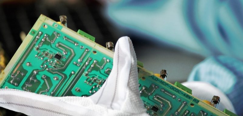
- Turnkey PCBA Solution: Unlike pure board shops, we understand the complexities of SMT assembly on thin substrates. We design custom carriers to ensure precision placement for 0201 and BGA components.
- Speed to Market: 24-hour DFM feedback and rapid prototyping services (3-5 days).
- Compliance: Fully certified under IATF 16949, ISO 9001, and UL.